Recently it seems like I have been running into alot of people wishing to replace wiring on the ecu, or repin it in general.
This is a quick walk-through for all of you who may either be considering replacing some of your wiring.
Here is a short list of tools you will need to tackle wiring harnesses.
-Exacto knife (for cutting away old harness tape)
-1mm or smaller slotted precision screw driver (like in this set: Here
-Stranded wire strippers (like these ones:Here )
-Multimeter (if you dont know how to use one, then you probably shouldnt be diving into your harness...)
If you plan on wanting to do harness work without splices, then its pretty important that you get one of these: Here
Tweak'd Performance can get you the terminals and connectors if you need them. Here
You will also obviously need some wire (which is discussed later)
Now... onto the fun stuff....
The first thing I reccomend anyone doing harness work do is familiarize themselves with how to read the OEM wiring harness diagrams. The instructions can be found in the BGB, which I dont plan on adding to this post for the sake of space. You can PM me if you would like a particular diagram, but the electrical wiring diagrams from Toyota arent that expensive...
Before deciding on replacing a wire, it is important that you ohm out the wire (and shielding where applicable) before deciding that it needs replacement.
The BEST way to ensure a solid connection when ohming out the wires is to first pull the terminal pin out of the ECU connector, and here is where things get a bit tricky. The BGB has pictures for how to do this, but I drew out a few of my own for you because I think they are better")
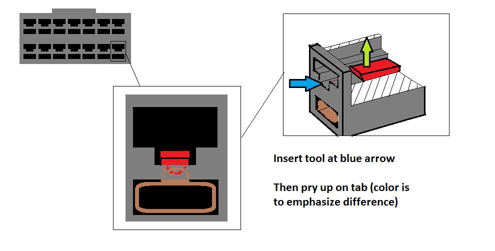
Uploaded with ImageShack.us
Then with the ECU pin removed, with an alligator clip attachment on your ohmmeter clip it to the terminal. Next after referencing the bgb as to the location of the termination point of the wire in the engine, touch the second end of the ohmmeter to the engine side pin and check to see if there is a solid connection. If there is a good connection, then it may be time to replace the sensor...
If you have no solid conneciton then its time to move on to creating a patch harness...
-Obtain a length of 18awg copper primary wire for signal wires (or 22awg tefzel) or if dealing with a shielded cable be sure to use something like RG316U coaxial. I have heard that you can also use something like r59 thin type coax as well, but the OEM's used RG316... Basically you want to try and replace whatever wire you took out with an equivalent one...
-Crimp on a new ecu terminal and a new connector terminal using your crimper. For shielded wire, you will need to splice a length of primary wire to the sheilding and put a round bolt through terminal on the end of that wire.
-Cut a small hole in the rubber boot on your firewall and feed the wire through
-Plug in your new terminals into the correct holes, plug em back in and you are good to go!
I will post more pictures later on
This is a quick walk-through for all of you who may either be considering replacing some of your wiring.
Here is a short list of tools you will need to tackle wiring harnesses.
-Exacto knife (for cutting away old harness tape)
-1mm or smaller slotted precision screw driver (like in this set: Here
-Stranded wire strippers (like these ones:Here )
-Multimeter (if you dont know how to use one, then you probably shouldnt be diving into your harness...)
If you plan on wanting to do harness work without splices, then its pretty important that you get one of these: Here
Tweak'd Performance can get you the terminals and connectors if you need them. Here
You will also obviously need some wire (which is discussed later)
Now... onto the fun stuff....
The first thing I reccomend anyone doing harness work do is familiarize themselves with how to read the OEM wiring harness diagrams. The instructions can be found in the BGB, which I dont plan on adding to this post for the sake of space. You can PM me if you would like a particular diagram, but the electrical wiring diagrams from Toyota arent that expensive...
Before deciding on replacing a wire, it is important that you ohm out the wire (and shielding where applicable) before deciding that it needs replacement.
The BEST way to ensure a solid connection when ohming out the wires is to first pull the terminal pin out of the ECU connector, and here is where things get a bit tricky. The BGB has pictures for how to do this, but I drew out a few of my own for you because I think they are better

Uploaded with ImageShack.us
Then with the ECU pin removed, with an alligator clip attachment on your ohmmeter clip it to the terminal. Next after referencing the bgb as to the location of the termination point of the wire in the engine, touch the second end of the ohmmeter to the engine side pin and check to see if there is a solid connection. If there is a good connection, then it may be time to replace the sensor...
If you have no solid conneciton then its time to move on to creating a patch harness...
-Obtain a length of 18awg copper primary wire for signal wires (or 22awg tefzel) or if dealing with a shielded cable be sure to use something like RG316U coaxial. I have heard that you can also use something like r59 thin type coax as well, but the OEM's used RG316... Basically you want to try and replace whatever wire you took out with an equivalent one...
-Crimp on a new ecu terminal and a new connector terminal using your crimper. For shielded wire, you will need to splice a length of primary wire to the sheilding and put a round bolt through terminal on the end of that wire.
-Cut a small hole in the rubber boot on your firewall and feed the wire through
-Plug in your new terminals into the correct holes, plug em back in and you are good to go!
I will post more pictures later on