Wiring Diagram for 205 speed sensor

If anyone can help, looking for the wiring pinouts for the 3 pin speed sensor at the sensor, it would be much appreciated.
 

aus jd 2703

New member
i believe this is what you want.
off my head im not sure of how many pulses per klm etc but can find it.
 

Attachments

  • S08-ToyotaSpeedSensor.pdf
    103.7 KB · Views: 514
Thanks.....if Toyotas sensors are the same this should work, the one I have is a the later model....Would you happen to have the wire color code?
 

l0ch0w

New member
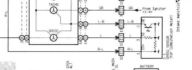
If you plan on running this into your standalone, I would really suggest shielding it... Its fine for feeding the tach, but it wont be so good for a DPO into your standalone if you plan on gear based boost control, traction control, flat shift etc... Its a VR sensor, not hall based so the likelihood for interference is high.

If you want, I can provide you with the open barrel terminals, and a length of wire to feed into your EMS. After running it into your EMS then you can use a digital output to your tach...
 
Andrew, thanks for the offer, the signal wire is currently shielded, I'm cleaning up a part of my harness. Since I installed the stack I no longer need the mechanical pigtail coming off the sensor & since I have a few of the 205 vss, its time to put one in....I actually used the single shielded wire for the oe ox1 to jumper box, way back when....I also pick up my tack for the stack directly from the msd.
 

l0ch0w

New member
Didnt mean to say tach, meant to say Speedo... im a dunce...

Are you just trying to get your stack to output speed? Have you thought of tapping into your ABS wheel speed sensors and then integrating traction control instead? That would be cool seeing as you have like eleventy-billion horsepower...
 

l0ch0w

New member
Maybe this will clarify things:

speedsensorst205.png
 
Top