DIY Electronics projects for ST185, want your Ideas

zf_165_gt

New member
Hi
i am working a lot on electronics a a hobby and I am a Professional programmer.
i like unseen projects involving microcontrollers and engine sensors, taking actions with those parameters.

Here's a list of my past and current projects, I would like to know your suggestions on what would be useful on the ST185, or anything 3S-GTE related
As I own 2 3S-GTE powered cars with standalone EMS, hacking the senor input of stock ecu is not my favorite thing, but if it helps a lot of people it should be available.

it could be instrumentation tools , like an turbocharger efficiency meter, electronic fuel pressure meter with junkyard parts( i will make one someday)
it could be simple analog projects too. I want your suggestions thanks
JF

In the past I built :
3S-GE with chipped civic ECU and civic distributor( was what i wanted to do for my first 3S-GTE , went megasquirt instead )
3S-GE and GTE megasquirted
a digital shift light( rpm switch)
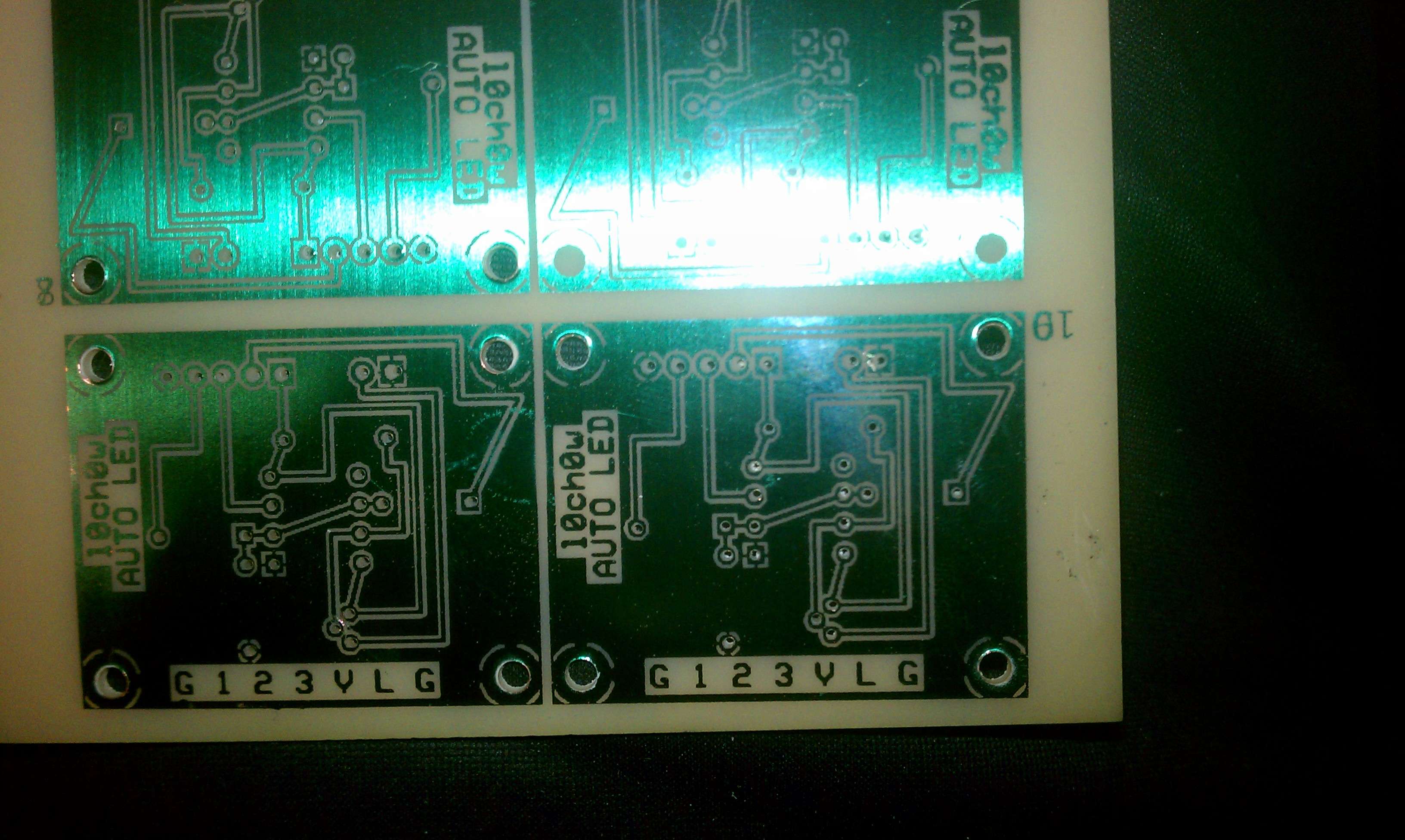
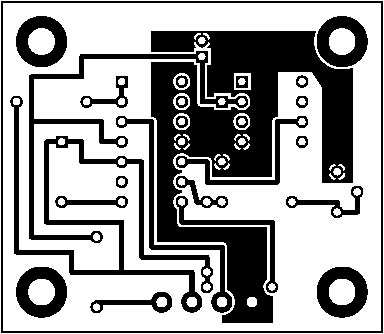
a 10 led display to show how much you floor your engine
an AFM simulator for the USDM 3S-FE engine ( would be portable to the GTE i think...) project abandonned after successfull proof of concept in favor of a megasquirt. might just do it again for pride..
an accelerometer circuit with a 128x64LED screen quite like a g-tech but with more power, whit it's main feature being a ball moving with forces applied on the circuit.

what i am building now:
IAC controller ,let's just say standalone EMS dont always have enough output so I am doing things by myself... cough cough :bangshead: Autronic SMC :bangshead:
universal dataloging system capable of drawing dynocharts(power applied on the car vs engine speed)and other parameters with cellphone

what I would want to in the near future:
GM solenoid boost controller circuit
an Ignition advance gauge, yes a gauge on your dashboard showing the advance at cyl1 just like a timing ligth

in the future someday:
a simple proof of concept standalone ECU (I dont want to really reinvent the wheel)
 

celigts

New member
How about something that lets us replace our gauge clusters with custom gauges or something along those lines? I dislike the stock colors, lighting and he fact thy the boost gauge is so slow and ugly.
 

underscore

Well-known member
At some point I wanna build something similar to the R34 Skyline multi-function display, with a screen that flips up out of the dash and gives all the info you'd normally get from a pile of aftermarket gauges. Then have it display either preset gauges or anything that is too high or too low. And also tie it to some kinda EMS, where it switches to a safer tune until everything is within range and it lets you go full tilt.
 

zf_165_gt

New member
@celigts , tach signal is a frequency input, speedometer it depends if you have a speed sensor on the transmission or not, the other gauges are analog voltages if my memory serves right,
you would need something to convert frequencies for your new gages if they work with different ones, and some values mapping for the analog gauges again. it would in my opinion need a microcontroller and some circuitry to do those things if you want to be able to put gauges which are really not meant to be there. quite a job but should be portable to any car with any clusters afterward... a cluster conversion interface ...

2 frequencies i think ,
1 for tach ( you need to use another frequency on the output if you want a tach for a car with a different number of spark event for the same engine revolution),
1 for speed sensor(if the speedometer you chosed is counting a different number of pulse)
a system to convert values from your oem analog sensors TO work with the gages you want to use now.( curves that the MCU use to determine the value to be sent to the new gages).

a circuit like that could make a lot of cluster conversion a piece of cake.while still cost less than 100$ for a DIY.(my opinion considering my techniques and tooling)
it should not be bigger than a big TV remote controller

for the stock boost gage,to begin , the PIM sensor is fast enough for what you want , your ecu uses it and its fine, i presume the slow speed if change is because of the gage 'resistance to change' it's hysteresis, it prevents sudden spikes that afraid people, but slows the overall change rate, oil pressure gages are like that, I never tried but i think it could be adjusted if the cluster removed and the oem boost gage tampered with to find a fast enough rate ,and be accurate, at the same time, while still in there include a measurement unit on the faceplate... i hate it when it's meaning nothing.the stock PIM sensor could go (correct me if i am wrong) to about 15 psi?? it would be interesting to be able to read that on this gage.

:eek:fftopic: the OEM clock could be hacked to display data also, it would be usefull, it is located at a good place to be seen while driving and it can display [0,9999] we could do something with that :rofl:

@underscore
my universal dataloging system is a bit like what you want, i can read a lot of sensors 8 analog ,2 frequencies , and can display them as i would like in real time,
it is mixing bluetooth and cellphone technology for display and do the computer work,saving logs, for a large display a tablet cellphone would be ideal if integrated to the car to show gages.
 

zf_165_gt

New member
Just tought about that,
we have an electronic bleed valve on the wastegate actuator, we should take control of this with a circuit ,we all throw it away and install manual MBC or expensive EBC.
the STOCK ecu already use it as an EBC.. :crazy: why not us
we should maximize the use of the hardware we already have if possible.
 

phattyduck

New member
zf_162_gt":3180bpc4 said:
Just tought about that,
we have an electronic bleed valve on the wastegate actuator, we should take control of this with a circuit ,we all throw it away and install manual MBC or expensive EBC.
the STOCK ecu already use it as an EBC.. :crazy: why not us
we should maximize the use of the hardware we already have if possible.
The stock TVSV on the ST165/ST185 is orifice-based, not PWM based. It is either open or closed, giving two boost levels. The ST205 does does use a PWM on the TVSV from what I understand though.

If there is a way to drill out the stock TVSV, you might be in business, otherwise it won't do much to have control over that signal.

-Charlie
 

underscore

Well-known member
zf_162_gt":51alpz4c said:
@underscore
my universal dataloging system is a bit like what you want, i can read a lot of sensors 8 analog ,2 frequencies , and can display them as i would like in real time,
it is mixing bluetooth and cellphone technology for display and do the computer work,saving logs, for a large display a tablet cellphone would be ideal if integrated to the car to show gages.

Sounds pretty slick, do you have any more info on it?
 

zf_165_gt

New member
@underscore
I dont want to disclose every aspect of it in fear of having my idea stolen.
I dont intend to commercialise it, but I dont want anyone making money with mi ideas.

it consist of two programs, one on the circuit reading data and sending it , the other is the interface and data analysis program. I may have or not talked about its most important goal, being able to make dynocharts showing torque vs RPM much like a G-TECH but with a lot more data being shown, and saved.
it runs a 32b microprocessor @12mhz and conditioning circuitry for sensor input, a specific group of cellphones(a large group that is quite popular now) for which i programmed an application to communicate with my other board.

I decided to give the maximum number of analog input , at 8 you should not need all of them, I dont myself need more than 6
the beauty in my concept is the cellphone side should be able to display anything you want as each input will have it's own configuration curve, so as long you know which AFR sensor you use, you can translate voltage into ratios. this works with every analog input, so PSI, deg celcius, everything.

for the frequency it is similar, in my case i want the first frequency to be divided by 0.06 which gives me RPM(1 coil 4 cylinder), another formula can be used on the secondary frequency input to give car speed, etc.. use your imagination.
it is not meant for knock sensor input, I have an idea for that but it is not for now.

the hardware side is not too hard to build ,i did not spend 100$ on it yet, but i cost me already one full week of vacation programming the thing, every component can be bought from Digikey and should not require someone extremely skillfull to build.

when i have fully tested it i will show you pictures.
 

MWP

New member
8 analog isnt anywhere near enough.
People who are serious about tuning (ie, the people that will pay decent $$s for your product) will want to log per-cyl EGT's, multiple coolant temps, fuel & oil pressures, intake/pre-ic/post-ic/inlet air temps, etc.

The car electronics project im working on has 16 analog, 8 digital inputs and CAN, and its main purpose isnt even logging (though it will do as well).
Ill be running a STM32 microcontroller.
 

zf_165_gt

New member
@MWP
good to know i am not alone in this kind of project, we could put up something usefull to give to alltrac.net for everyone to build, for my part my Microcontroller as only 8 analog input , it's a cortex m0 based MCU, previously i did everything with Microchip PIC16 and PIC18 and probably wont go back to it, with the STM32 you will have a lot of processing power in comparison to my m0 ;).
 

MWP

New member
My project is taking up every bit of spare time i have.
I am working on making it a commercial product as i see a good opening for it. There is some products around that already do it, but i should be able to do it cheap and better in a few ways.
Its a huge project though for 1 person :(
(im not saying what it is for obvious reasons ;) )
 

zf_165_gt

New member
that's why i am not telling what phone or MCU brand i use and how they comunicate with each other, anyone with programming skills can come up with alogrythms to do it but will need to chose their hardware themself.
;)
 

MWP

New member
Well the phone has to be iPhone or Android... any other choice would be silly.
Coms would be via either Bluetooth of WiFi.
 

l0ch0w

New member
Im pretty good at making and designing the circuit boards :)

Right now im designing a PWM controller for my MAC boost solenoid so that I can just adjust boost levels, and switch between cruise and race mode with a push pull pot.

imag0042dd.jpg

By alochow at 2011-12-19

boostcutdefender.png

By alochow at 2011-12-28

Ive also copied HKS's discontinued fuel cut defender.
 

zf_165_gt

New member
@l0ch0w nice job with the PCB, the FCD is something popular, never needed it myself.
if you're interested in a common project PM me.
 

l0ch0w

New member
Havent needed the FCD myself either... I just figured so many people could use one that I decided that I could maybe make some money on em.

Id personally be interested in a double din touch screen lcd that can run both a "carputer" for tuning my standalone (haltech) and also be the radio...

Im not really good at the programming side of stuff, but I can hold my own on the hardware side.
 
Top