TheNubkins
New member
For quite some time my tach has been laggy, buggy, and lately almost completely dead. I searched around and figured out the problem was two faulty capacitors on the circuit board for the tach gauge. Here is a walkthrough of what I did to repair my gauge. This is perhaps not the best, or the correct way of doing this, but it is what I did and it worked for me. As per usual, I assume no responsibility for anything that may occur to you, your vehicle, or anything related to you by following these steps or anything resembling what I've done. There is a risk of damaging your gauge, your vehicle, or yourself. Also as a note, I did not disconnect the battery for this. You may wish to do this beforehand, although I'm not sure if the auto-tilt feature of the car after the key has been removed will still function.
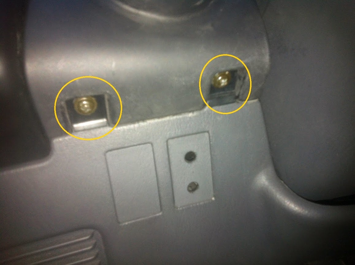
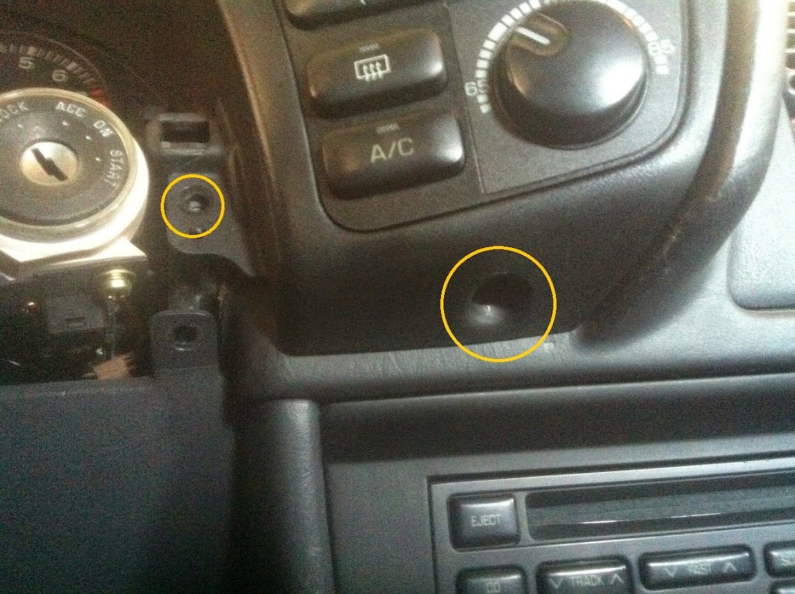
Step 1 - Begin by removing the two screws to the left of the steering column.
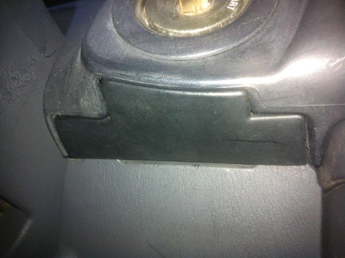
Step 2 - There is a small trim piece to the right of the steering column that is concealing two more screws. This is located below the ignition. Remove this plastic trim piece and the two screws.
Step 3 - Insert the key into the ignition, tilt down on the steering wheel, and remove the key while continuing to apply light downward pressure on the steering wheel. As you remove the key the wheel will lower a bit futher allowing you to pop out and remove the steering wheel surround that was just unscrewed in the first two steps.
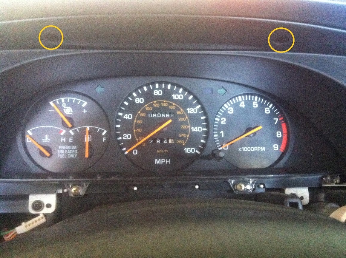
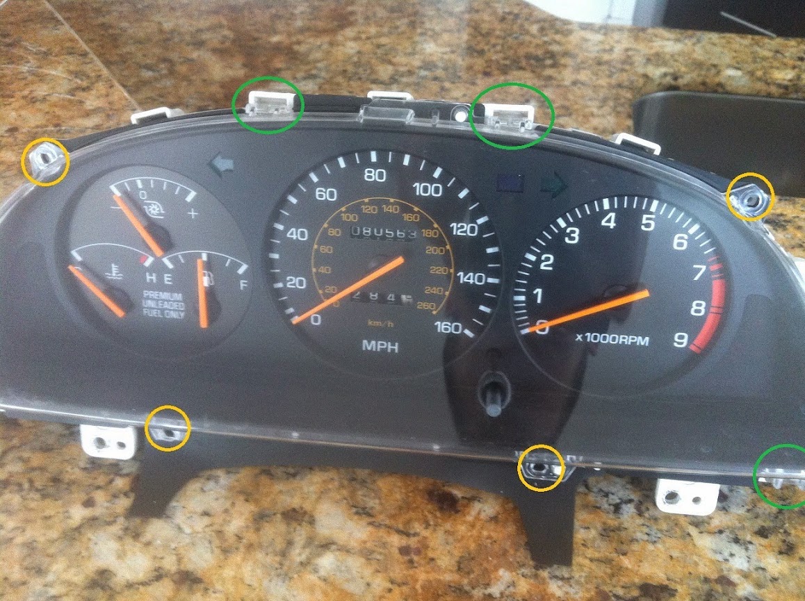
Step 4 - You now need to remove the trim piece surrounding the upper 180 degree portion of the gauge cluster. There are five mounting screws circled in the pictures below. Ignore the electrical connectors, circled in green, as they are for a gauge I have mounted in the first trim piece that was removed.
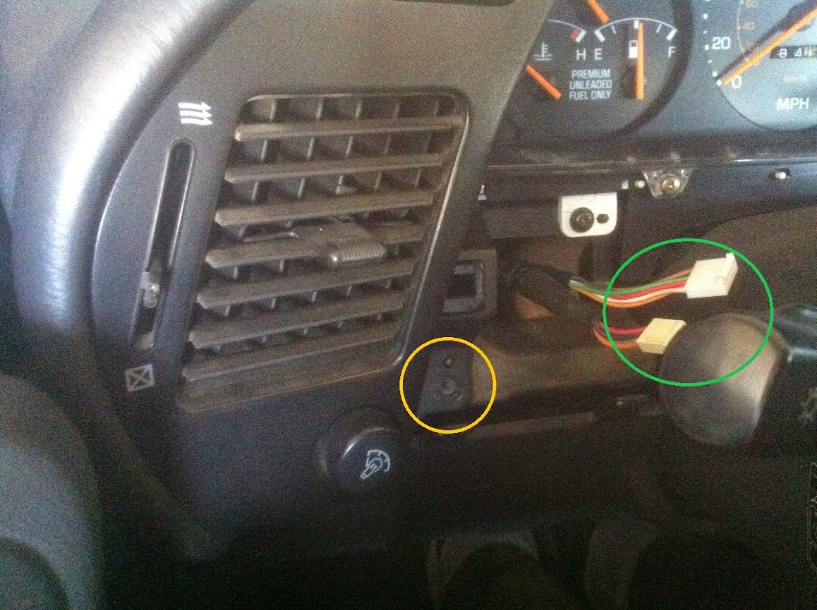
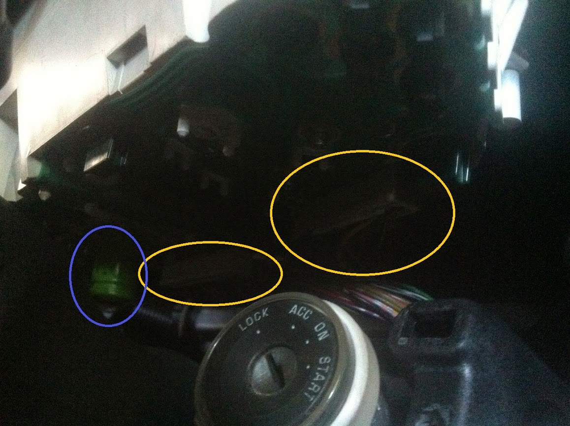
Step 5 - With some gentle prying you can losen the left and the right portion of the large plastic trim. Working on the right side of the dash that houses the HVAC controls, I removed the wired connector, circled in yellow, by depressing a plastic release indicated by the green arrow. The rest of the connectors on this board I kept intact.

Step 6 - To the left side I disconnected the plugs for the interior backlight dimming switch, and the fog light switch.

Step 7 - This allowed me to pull the trim piece out from behind the steering wheel, rotate it and lay it as shown while still connected to the electrical harness. Here it is out of the way and you can move on to removing the gauge cluster itself.

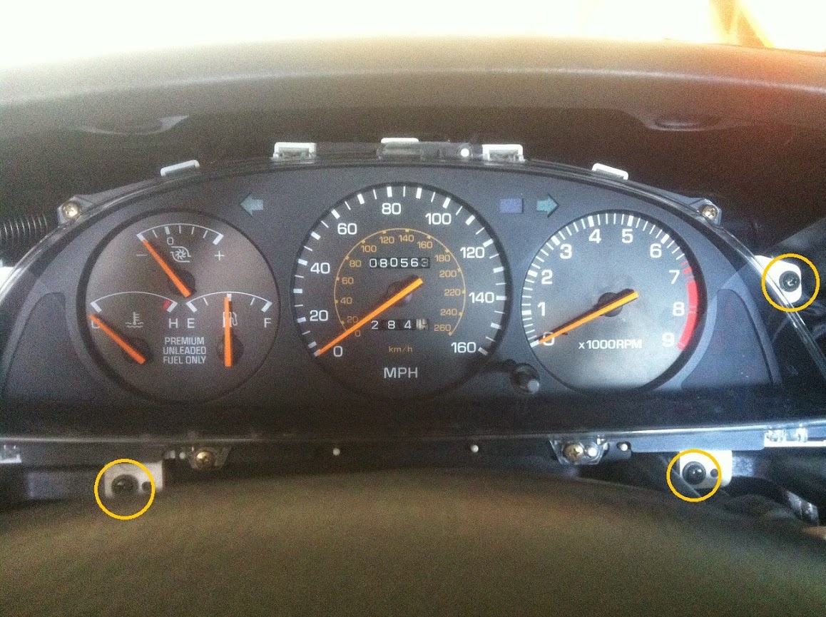
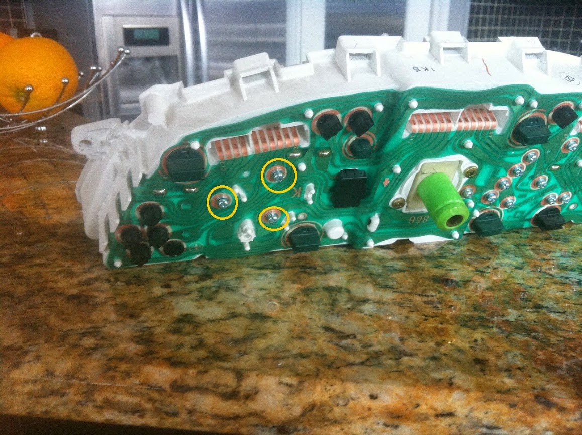
Step 8 - Remove the four screws, three of which are pictured below and circled. The fourth is to the left out of the picture frame...oops.")
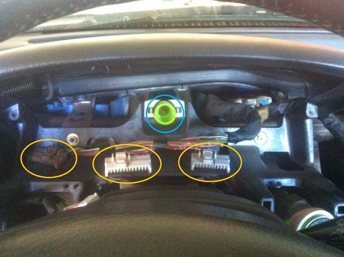
Step 9 - Gently pull the cluster towards you, and as you do so begin to tilt it so the gauge faces aim up. The object circled in blue connects for the speedo and should have disengaged on it's own from the mating part attached to the car. There are three electrical clips that need to be removed, and the release tab on them is large and easy to operate with no guesswork. Two of these electrical clips are circled, the third is to the left of the speedo port but is not visible in the picture.
Step 10 - You can now remove the gauge cluster. Here you can see the speedo connector, and the three electrical connectors you just removed.
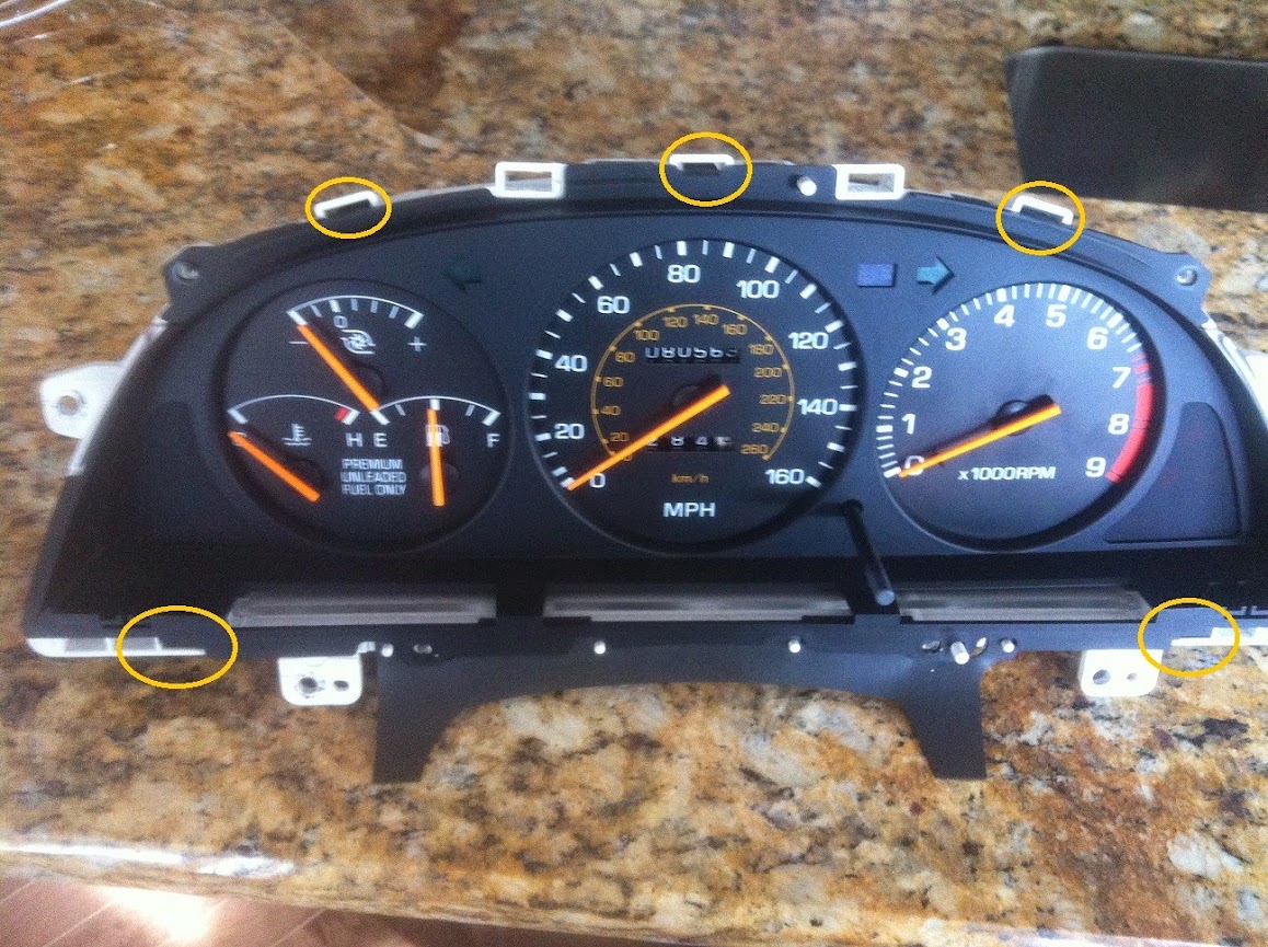
Step 11 - Remove the four screws securing the plastic faceplate, and depress the tabs while gently pulling forwards on the faceplate to remove it. There is another tab out of the frame of the picture...another oops. Obviously I'm no photographer.
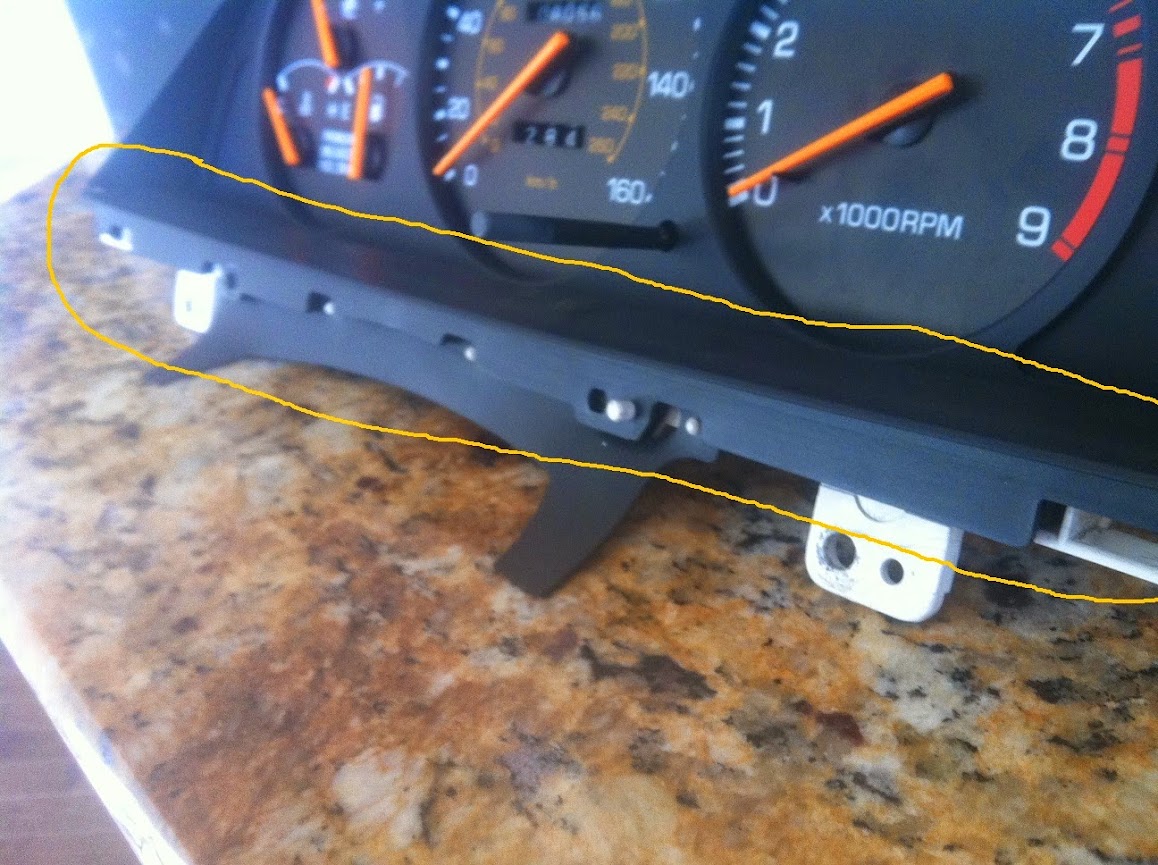
Step 12 - This black lower trim slides out, easily. It is held in position by clips and is guided on a small inset track on the left and right of the cluster.
Step 13 - Depress the tabs for the gauge shroud and remove it.
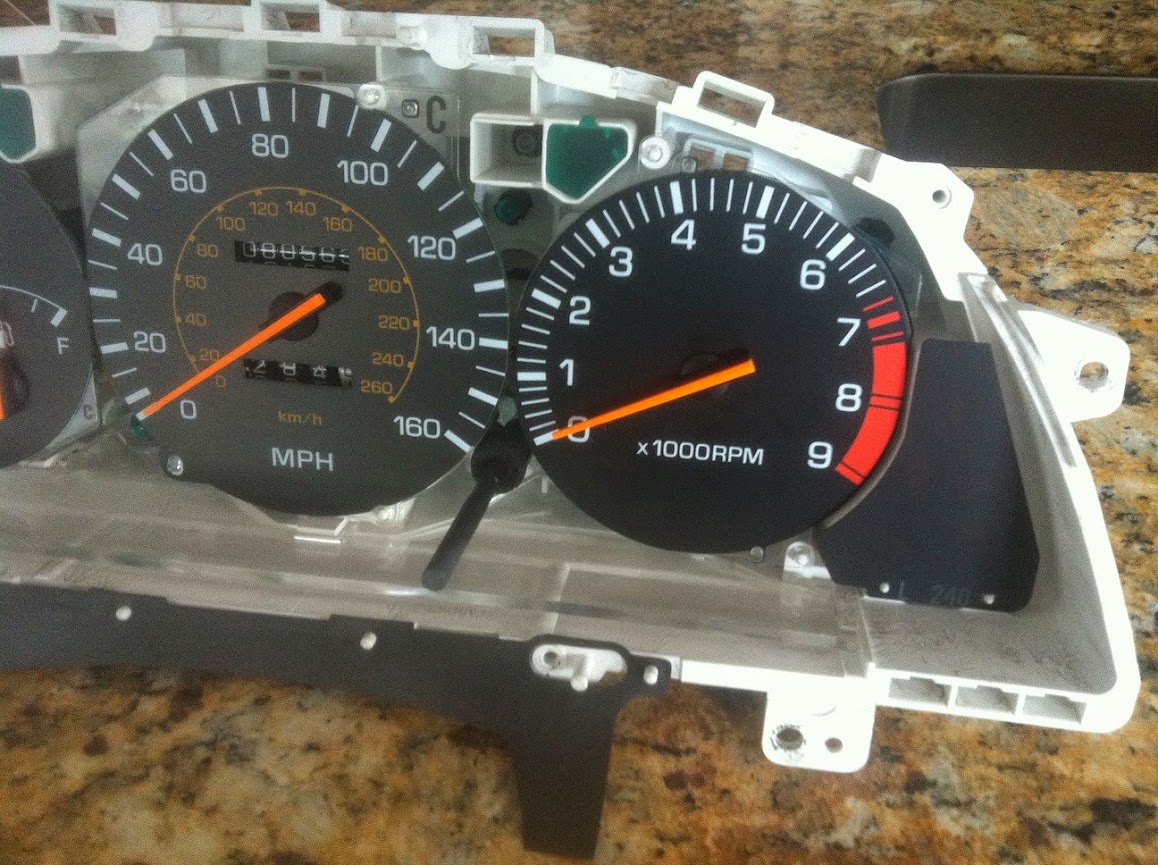
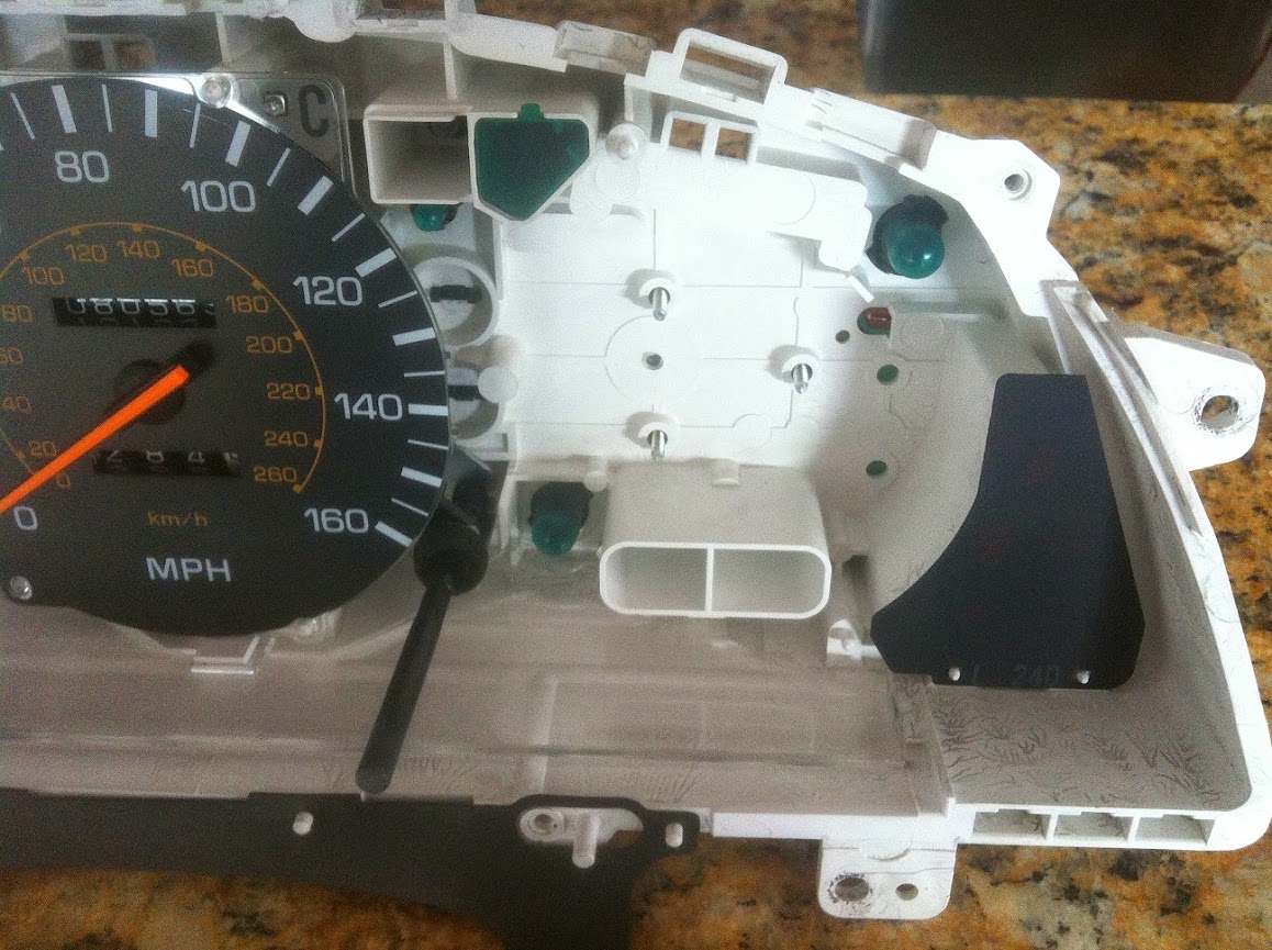
Your gauges should now appear like this.
Step 14 - Behind the tach there are three screws securing the tach circuit board and gauge assembly to the housing. Unscrew all three of these until you can gently remove the tach from the housing.
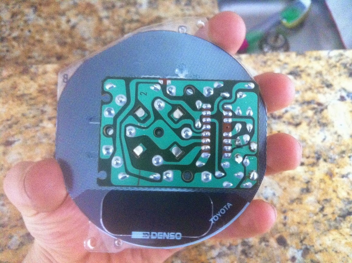
Here is the backside of the circuit board for the tach, still attached to the front gauge face.
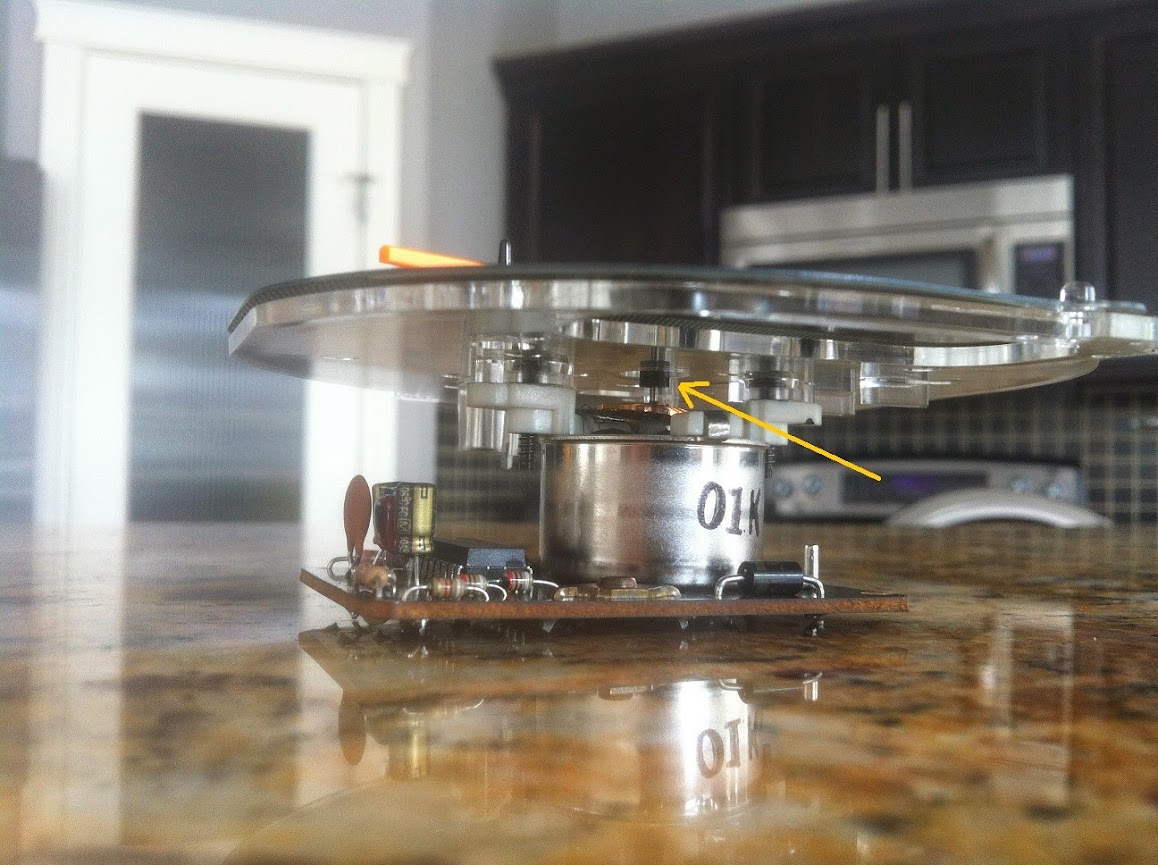
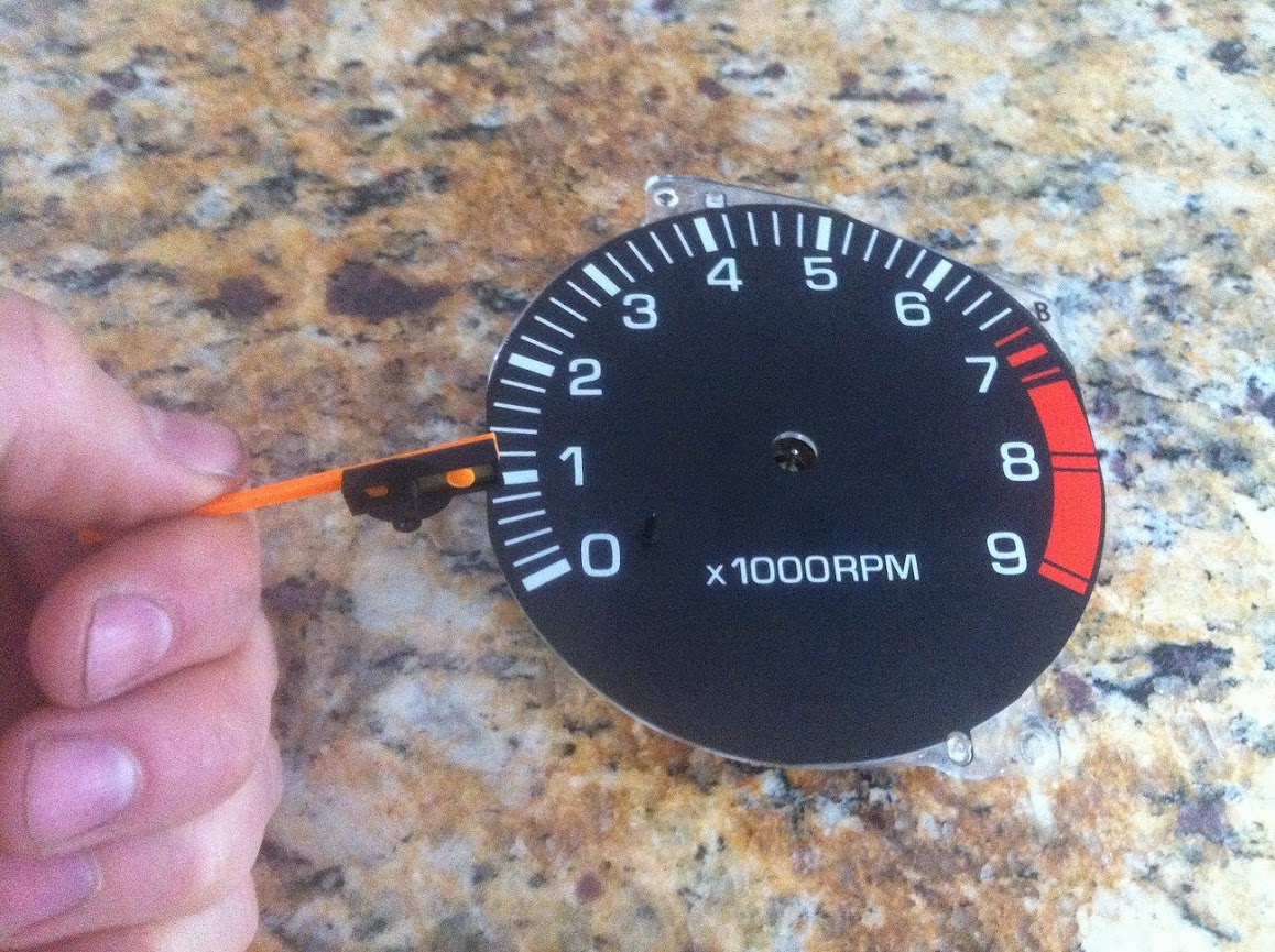
Step 15 - You will need to remove the gauge needle, and I stress this highly, VERY CAREFULLY. The needle slides over a small cylinder as you can see pictured below and indicated with the yellow arrow. I used a small flat head screw driver to gently put even force from the arrow side until I was able to slide the needle up and off. DO NOT pull on the needle extremities as it will most likely break off. If you must pull, pull evenly from the center hub of the plastic needle.
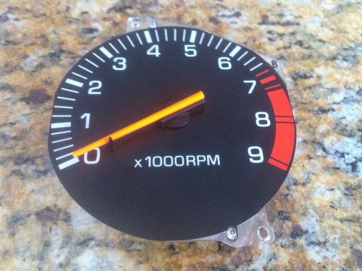
Victory will look something like this.
Step 16 - The gauge faceplate is comprised of two parts. A clear plastic backing providing the structural support, and the detailed analog print, also made of a type of plastic. These two are glued together with small square adhesive "pads" of glue placed over the screw mounting holes. I slid a very very thin flat head screwdriver between the two, and pushed through the glue pad working a bit at a time. I did not pry upwards in fear of creasing or damaging the printed gauge face. When you break both glued sections you can remove the face.
Step 17 - Unscrew the two black screws securing the plastic gauge structure to the board.

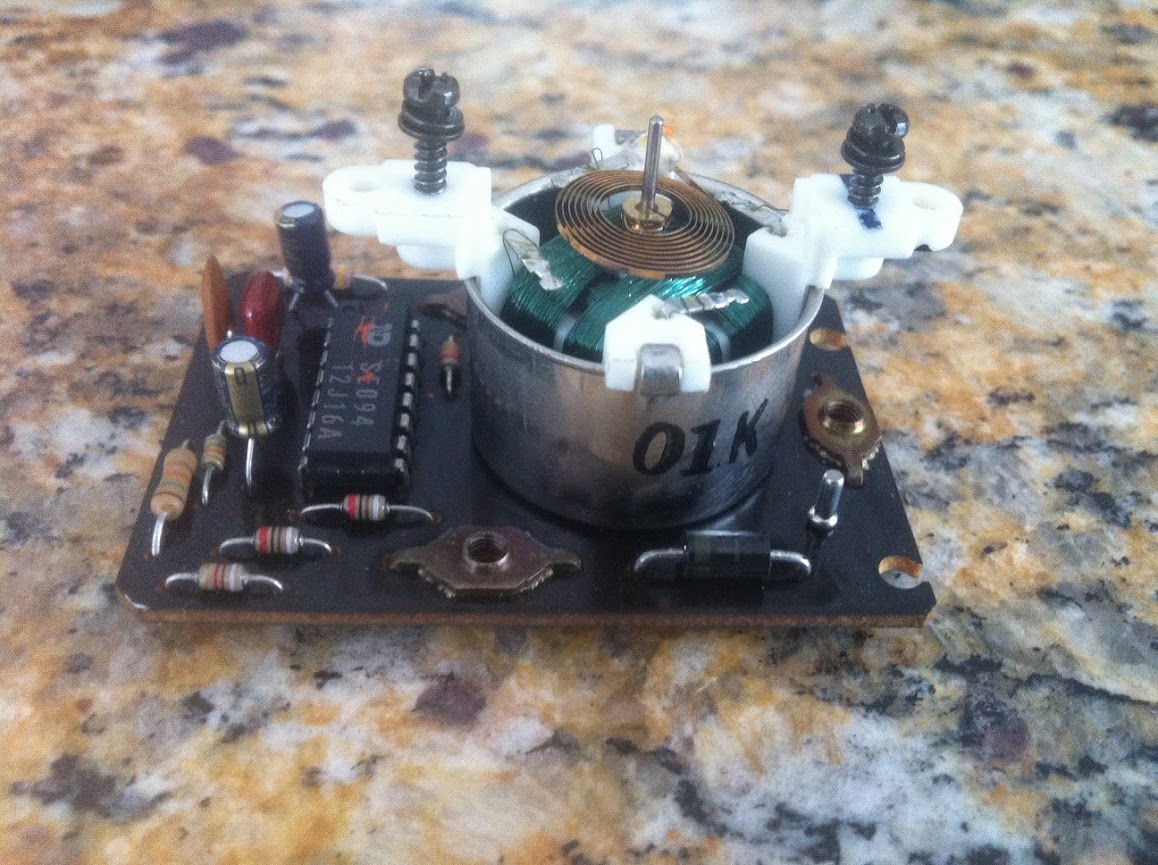
You are now left with the board itself. The culprits of the malfunctioning board are these two capacitors. In my case it was only the one, but I replaced both for good measure. These are 10 micro-farad 25 volt 105*C capacitors. They were about 35 cents each.


NOTE THE POLARITY OF THE CAPACITORS!!! They will be marked on one side to indicate the negative terminal. To remove the capacitors I used a soldering gun, heated the solder at the back of the board while pulling gently on the capacitor. As soon as the solder liquefies it should pop out. Do not apply excessive heat to the board. Once removed I slid the new capacitor through, and soldered the new leads in, and finally snipped the excess wire on the backside of the board(which is the side of the board you are doing the soldering by the way).
Step 18 - Reconstruct the gauge cluster as you removed it, but I advise you leave off the plastic gauge cover and the gauge needle for now. This is because when the gauge has power, but the vehicle is not running, it will "zero" itself. This position is where you need to reattach the needle with it resting on the lower needle stop near the 0 on the analog tach scale. If you do not do this, and just put the needle back on with the cluster out of the car then once it has power with the key in the ignition and goes to "zero" itself, you will find the needle to be sitting around 1000-2000rpm with the engine off.
Step 19 - Reinstall everything to the point where the gauges are back in the car, but the trim pieces are still free. Stick the key in the ignition and turn to "on". If you watch the small cylinder the needle attaches to very closely you will see it spin clockwise just a bit as you cycle the key. With the key turned to "on" put the needle back on. This is where I hooked my laptop up and started the car and verified the tach needle was placed in the correct location based on what my tuning software said my motor speed was. Another method is to have your motor warm and if you recall where your car idled at you can compare your new tach reading to that and adjust accordingly. It won't be as accurate but it'll get you close. I'm sure there are other ways of doing this.
Step 20 - Reinstall the remainder of the trim pieces, not forgetting to hook up the electrical connectors you removed earlier.
Hopefully this helps someone out there.
Step 1 - Begin by removing the two screws to the left of the steering column.
Step 2 - There is a small trim piece to the right of the steering column that is concealing two more screws. This is located below the ignition. Remove this plastic trim piece and the two screws.
Step 3 - Insert the key into the ignition, tilt down on the steering wheel, and remove the key while continuing to apply light downward pressure on the steering wheel. As you remove the key the wheel will lower a bit futher allowing you to pop out and remove the steering wheel surround that was just unscrewed in the first two steps.
Step 4 - You now need to remove the trim piece surrounding the upper 180 degree portion of the gauge cluster. There are five mounting screws circled in the pictures below. Ignore the electrical connectors, circled in green, as they are for a gauge I have mounted in the first trim piece that was removed.
Step 5 - With some gentle prying you can losen the left and the right portion of the large plastic trim. Working on the right side of the dash that houses the HVAC controls, I removed the wired connector, circled in yellow, by depressing a plastic release indicated by the green arrow. The rest of the connectors on this board I kept intact.
Step 6 - To the left side I disconnected the plugs for the interior backlight dimming switch, and the fog light switch.
Step 7 - This allowed me to pull the trim piece out from behind the steering wheel, rotate it and lay it as shown while still connected to the electrical harness. Here it is out of the way and you can move on to removing the gauge cluster itself.
Step 8 - Remove the four screws, three of which are pictured below and circled. The fourth is to the left out of the picture frame...oops.
Step 9 - Gently pull the cluster towards you, and as you do so begin to tilt it so the gauge faces aim up. The object circled in blue connects for the speedo and should have disengaged on it's own from the mating part attached to the car. There are three electrical clips that need to be removed, and the release tab on them is large and easy to operate with no guesswork. Two of these electrical clips are circled, the third is to the left of the speedo port but is not visible in the picture.
Step 10 - You can now remove the gauge cluster. Here you can see the speedo connector, and the three electrical connectors you just removed.
Step 11 - Remove the four screws securing the plastic faceplate, and depress the tabs while gently pulling forwards on the faceplate to remove it. There is another tab out of the frame of the picture...another oops. Obviously I'm no photographer.
Step 12 - This black lower trim slides out, easily. It is held in position by clips and is guided on a small inset track on the left and right of the cluster.
Step 13 - Depress the tabs for the gauge shroud and remove it.
Your gauges should now appear like this.
Step 14 - Behind the tach there are three screws securing the tach circuit board and gauge assembly to the housing. Unscrew all three of these until you can gently remove the tach from the housing.
Here is the backside of the circuit board for the tach, still attached to the front gauge face.
Step 15 - You will need to remove the gauge needle, and I stress this highly, VERY CAREFULLY. The needle slides over a small cylinder as you can see pictured below and indicated with the yellow arrow. I used a small flat head screw driver to gently put even force from the arrow side until I was able to slide the needle up and off. DO NOT pull on the needle extremities as it will most likely break off. If you must pull, pull evenly from the center hub of the plastic needle.
Victory will look something like this.
Step 16 - The gauge faceplate is comprised of two parts. A clear plastic backing providing the structural support, and the detailed analog print, also made of a type of plastic. These two are glued together with small square adhesive "pads" of glue placed over the screw mounting holes. I slid a very very thin flat head screwdriver between the two, and pushed through the glue pad working a bit at a time. I did not pry upwards in fear of creasing or damaging the printed gauge face. When you break both glued sections you can remove the face.
Step 17 - Unscrew the two black screws securing the plastic gauge structure to the board.
You are now left with the board itself. The culprits of the malfunctioning board are these two capacitors. In my case it was only the one, but I replaced both for good measure. These are 10 micro-farad 25 volt 105*C capacitors. They were about 35 cents each.
NOTE THE POLARITY OF THE CAPACITORS!!! They will be marked on one side to indicate the negative terminal. To remove the capacitors I used a soldering gun, heated the solder at the back of the board while pulling gently on the capacitor. As soon as the solder liquefies it should pop out. Do not apply excessive heat to the board. Once removed I slid the new capacitor through, and soldered the new leads in, and finally snipped the excess wire on the backside of the board(which is the side of the board you are doing the soldering by the way).
Step 18 - Reconstruct the gauge cluster as you removed it, but I advise you leave off the plastic gauge cover and the gauge needle for now. This is because when the gauge has power, but the vehicle is not running, it will "zero" itself. This position is where you need to reattach the needle with it resting on the lower needle stop near the 0 on the analog tach scale. If you do not do this, and just put the needle back on with the cluster out of the car then once it has power with the key in the ignition and goes to "zero" itself, you will find the needle to be sitting around 1000-2000rpm with the engine off.
Step 19 - Reinstall everything to the point where the gauges are back in the car, but the trim pieces are still free. Stick the key in the ignition and turn to "on". If you watch the small cylinder the needle attaches to very closely you will see it spin clockwise just a bit as you cycle the key. With the key turned to "on" put the needle back on. This is where I hooked my laptop up and started the car and verified the tach needle was placed in the correct location based on what my tuning software said my motor speed was. Another method is to have your motor warm and if you recall where your car idled at you can compare your new tach reading to that and adjust accordingly. It won't be as accurate but it'll get you close. I'm sure there are other ways of doing this.
Step 20 - Reinstall the remainder of the trim pieces, not forgetting to hook up the electrical connectors you removed earlier.
Hopefully this helps someone out there.